Unique Pulse Solutions
November 2011
|
Although most pulse products are sold to either protect expensive electrical equipment or provide additional outputs, they can also solve tricky challenges in pulse metering applications. Specialized pulse solutions have become an area of expertise for Solid State Instruments in our efforts to satisfy our customer’s pulse-related needs. So what kind of tricky pulse problems do we solve? Well the list goes on and on… but there are three main categories that most of them fall under:
| ||||
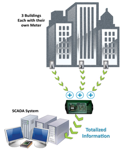 |
1. TotalizingBasic Description: Totalizers don’t just add pulses together, they can also calculate net energy use by using both positive and negative pulse input values. For example, in applications where energy is being generated while simultaneously being used to power certain aspects of the configuration, the customer may want to “net” out the amount of energy used. |
Example: 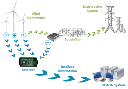
There are many types of applications where these types of configurations are needed and can be executed with the use of a Metering Pulse Totalizer. Click on the models below to learn more about their capabilities.
|
||
2. Pulse Links:Basic Description : | |||
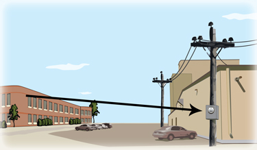 |
PRL-900 The PRL-900 can wirelessly transmit a pulse signal up to a distance of 1000 feet. It is equipped with 4 channels capable of operating in Form A or C. Great in applications where running wire is expensive or not feasible. | ||
Fiber Optic Transmission | |||||||||||||||||||||
|
OPL Series
The OPL can transmit a pulse signal up to a distance of 3 miles through multimode fiber optic cable. It is available in 1, 2, or 4 channels capable of operating in either Form A or C. * Also available in single-mode fiber for distance up to 18 miles. | |||||||||||||||||||||
DTMF Transmission |
|||||||||||||||||||||
| TT-4C and TR-4C
The TT-4C Transmitter and TR-4C Receiver use a DTMF (duel-tone, multi-frequency) signal to transmit up to a distance of a half mile through either an existing dedicated phone wire or alternative twisted pair wire. It is equipped with 4 channels capable of operating in either Form A or C. | |||||||||||||||||||||
Current Loop Transmission |
|||||||||||||||||||||
| PTR-1PS and CLR Series
The PTR-1PS Transmitter and CLR Receiver transmit up to a distance of 2-4 miles (depending on the receiver model and wire size). All units operate in Form C, and the CLR Receivers are available in 1, 2, or 3 outputs. PTR-2PSThe PTR-2PS is installed near the pulse-receiving device and receives the pulse signal from the meter through a pair of wires up to a distance of 2,500 feet from the meter. It is equipped with up to 3 Form A outputs. | |||||||||||||||||||||
3. Pulse Conditioning:Basic Description *normal mode also referred to as long mode 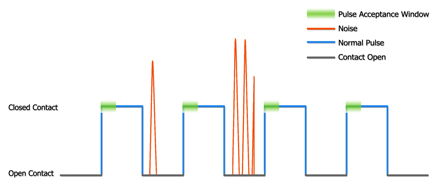
The diagram above demonstrates the opening and closing of a relay contact. Even though the noise spikes have sufficient enough voltage to close the contact, they are rejected from the pulse count because the length of time they each occur does not meet the pulse acceptance window. In other words, the pulse width of each noise spike is too short so they are ignored. Click on the models below to learn more about their capabilities.
If you ever come across a "tricky" pulse metering situation, contact the experts at Solid State Instruments... We may have just the solution you're looking for! | |||||||||||||||||||||