LMR-121PS Load Management Relay
The LMR-121PS load management relay is designed to make implementing load management applications easy, and provides two isolated solid-state dry contact outputs from a single Form A or C input. Output contacts are configured as Form C (K, Y, & Z) contacts. The first set of contacts is available for the customer’s use. The remaining set is designed for utility use and is located in the lockable utility compartment. In addition, an auxiliary voltage output is available in the customer compartment for powering additional related telemetry or equipment.*
*Note: To use the 120VAC Auxiliary Power Output, the relay must be powered
by 120VAC.
The typical application of the LMR-121PS is the utilities’ interface between the electric meter and data or load profile recorders, demand response equipment or customer-owned energy control systems. The LMR-121PS includes everything necessary to provide a customer with energy pulses in one compact, ready-to-use, weather-resistant enclosure.
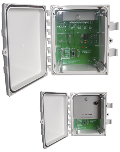
The LMR-121PS is internally divided into two compartments. Once installed, the upper compartment is normally locked and only accessible to utility metering personnel. It contains all of the electronics along with fusing that is coordinated with the fuses contained within the customer compartment. The lower compartment (customer compartment) contains a terminal strip, fusing, and output status LEDs for the pulse output and the auxiliary power supply. A on/off switch for the auxilary power output allows additional powered equipment to be easily turned on and off for operation and maintenance. The red and green LEDs light alternately upon changes of the KYZ input status.
The use of LEDs in the customer’s compartment allows a rapid visual check of the system’s performance by inexperienced personnel without requiring any additional test equipment. Because of the redundant, coordinated fusing in both the utility’s and customer’s compartments, the meter shop service coordinator can usually determine the location of the service problem as to either utility or customer responsibility by the simple question “are the LEDs flashing?” The double “K” lead coordinated fusing of the customer’s pulse output will prevent damage to the relay under almost any condition a user might cause such as that caused by excessive current, incorrect wiring, etc. The robust solid state switching devices are rated at 800V and 750mA giving maximum protection from lightning or transient voltage damage. The LMR-121PS has built-in transient protection for the solid state switching devices that eliminates the need for external or off-the-board transient suppressors.
| Electrical | |
|---|---|
| Power Input: | 120 VAC, 208-277 VAC. Burden: 10 mA at 120 VAC |
| Pulse Input: |
One Form C (3-wire) input with +13VDC wetting voltage on the K terminal; (Can also be used as one or two Form A inputs) |
| Pulse Output: |
One or two Form C dry contact solid-state outputs, one in the customer’s compartment and one in the utility compartment. The contacts are solid-state “no bounce” relays rated at 250VACVDC at 1/2 Amp. The maximum rating of the contacts is 100 VA. Factory fused at 1/2 amp. (3AG) |
| Contact On-State Resistance: |
2.3 ohms maximum, 1.7 ohms typical |
| Insulation Resistance: | 50 megohms typical |
| Operate and Release Time: |
Turn On Time - 8 mS typical; 20 mS MAX Turn Off Time - 1 mS typical; 5 mS MAX |
| Input/Output Isolation Voltage: | 2500Vrms |
| Auxiliary Voltage Output: | One 120VAC switched output available in customer compartment to power auxiliary load management equipment, fused at 1/2 AMP. Operates only with 120VAC input. |
| Mechanical | |
|---|---|
| Mounting: | Any position |
| Size: | 9.0’’ wide, 11.0’’ high, 4.50’’ deep |
| Weight: | 9 pounds |
| Type/Material: | NEMA 4X Fiberglass Case |
| Temperature | |
|---|---|
| Temperature Range: | -38º C to +70º C, -38.4º F to +158º F |
| Humidity: | 0 to 98% non-condensing |
| Available Options | |
|---|---|
| Input Voltages: |
125VDC, 15 - 48VDC, 12VAC/VDC. Contact Factory. |
All specifications are subject to change without notice.