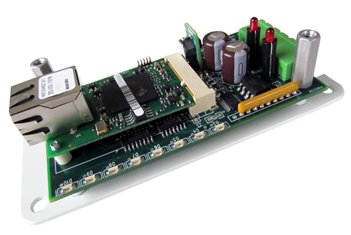
PMC-1 Pulse-to-Modbus Converter
The PMC-1 Pulse-to-Modbus Converter is a device designed to read, record and store pulses from two 2-Wire KY pulse inputs and provide access to the energy use and demand information using the Modbus TCP protocol. Pulse inputs are recorded in the count register and the equivalent energy value is calculated and recorded in the energy use register. The PMC-1’s inputs provide a +13VDC wetting voltage for the meters’ dry-contact outputs. Upon receiving each pulse from the meter, the PMC-1’s microcontroller converts the pulse to the kWh value and adds it to the energy use register. The instantaneous, average and peak demand (kW) are also captured and available in three separate registers for each channel. Average and Peak Demands are based on a 15 minute demand interval.
Energy use information collected and stored in non-volatile memory and accessible by using the RJ-45 Ethernet connection of the PMC-1. The Modbus protocol allows accessing the specific PMC-1 device using a unique IP address, and the register for the information of the pulse channel desired. A RS-232C DB9 serial port allows quick programming of the IP address and pulse value. A master reset capability allows all registers to be cleared.
The PMC-1’s bright red LED lamps indicate the Pulse input’s status at all times. Eight additional green LED’s indicate device and network status.
Read-only Registers accessible for each channel are:
- Cumulative energy since last reset or rollover (kWh)
- Instantaneous Demand (kW)
- Average Demand (kW)
- Peak Demand since last reset (kW)
- Time since last power up (seconds)
- Pulse Count since last reset (number)
Programmable values are:
- Pulse Constant (kWh/pulse) for each channel
- Pulse Value Type (2-wire or 3-wire)
- Reset all registers
Typical applications include:
- Provide real-time energy and power measurements for Energy Management Systems, Dashboards, software applications or web clients
- Access, View and Track Energy Use and Demand information
- Generate interval data and load profiles
- Demand Response program monitoring
- Utility submetering (electricity, gas, water, etc.)
- M&V Measurement and Verification of Energy Efficiency Measures
- Utility meter Verification
Specifications
| Electrical | |
|---|---|
| Power Input: | 120VAC by 12VAC wall transformer (included); Burden: 100 MA. at 120 VAC (12 Watts) |
| Pulse Input: | Two KY Form A (2-wire) inputs with +13VDC wetting voltage compatible with dry contact or open-collector transistor output. Detachable terminal block. |
| Maximum Input Pulse Rate: | 10 pulses per second |
| Pulse Value: | .001kWh/p to 655.35 kwh/p, in .0001 kWh increments |
| Output: | No Hardware outputs; Register reads only |
| Network Interface: | RJ-45 Ethernet |
| Protocol: | Modbus TCP |
| Demand Averaging Interval Selection: | 15 minutes |
| Peak Demand Reset, by channel: | Yes |
| Reset Cumulative Energy, by channel: | Yes |
| Reset Cumulative Raw Pulse Count, by channel: | Yes |
| Mechanical | |
|---|---|
| Mounting: | Any position |
| Size: | 2.30“ wide, 4.8” long, 1.50” deep |
| Weight: | 17 ounces |
| Temperature | |
|---|---|
| Temperature Range: | -38º C to +70º C, -38.4º F to +158º F |
| Humidity: | 0 to 98% non-condensing |
| Options | |
|---|---|
| Input Voltages: | 12VAC. Contact Factory. |
All specifications are subject to change without notice.
Documentation
PMC-1 Pulse-to-Modbus Converter Specification Sheet
PMC-1 Pulse-to-Modbus Converter Instructions V4
EXP Expansion Boards Specification Sheet
EXP Expansion Boards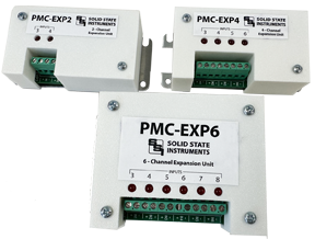
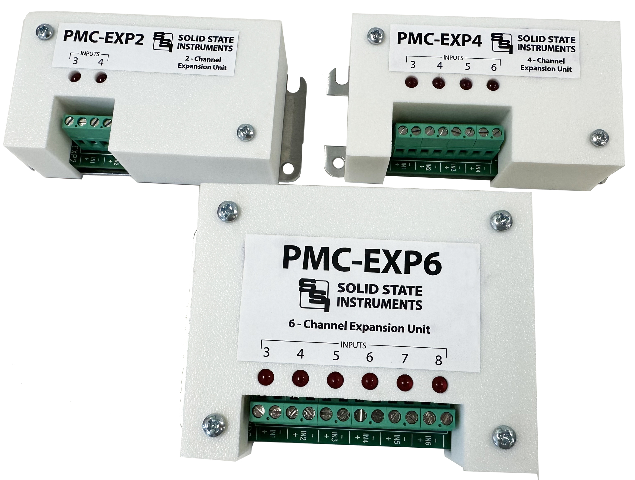
The EXP Expansion boards are designed for use with SSI’s PMC-1 V5 Pulse-to-Modbus Converter. They are available in 2-input, 4-input or 6-input models, allowing the PMC-1 to be expanded to a total of 4, 6 or 8 input channels respectively. No additional power supply is required to power the EXP boards since they are powered off the PMC-1. The EXP boards connect to the PMC-1’s main board by means of a ribbon cable. No configuration is necessary since the PMC-1 can identify which if any of the EXP expansion boards are installed.
Each pulse input provides a nominal +12VDC wetting voltage for the meters’ dry-contact output. Upon receiving each pulse from the meter, the PMC-1’s microcontroller converts the pulse to the kWh value and adds it to each channel’s energy use register. In addition, the accumulated raw pulse count is available for each channel.
Energy use information collected and stored in non-volatile memory and accessible by using the RJ-45 Ethernet connection of the PMC-1.
The EXP boards contain bright red LED lamps which indicate the Pulse input’s status at all times.
Typical applications include:
• Provide real-time energy and power measurements for Energy Management Systems, Dashboards, software applications or web clients
• Access, View and Track Energy Use and Demand information
• Generate interval data and load profiles
• Demand Response program monitoring
• Utility submetering (electricity, gas, water, etc.)
• M&V Measurement and Verification of Energy Efficiency Measures
• Utility meter Verification
Specifications
| Electrical | |
|---|---|
| Power Input: | No power required. EXP boards are powered from the PMC-1 V5 |
| Pulse Input: | Two to Six KY Form A (2-wire) inputs with +12VDC wetting voltage compatible with dry contact or open-collector transistor output. Detachable terminal block. |
| Maximum Input Pulse Rate: | 10 pulses per second |
| Pulse Value: | .001kWh/p to 655.35 kwh/p, in .0001 kWh increments. |
| Output: | No Hardware outputs; Register reads only |
| Protocol: | Modbus TCP |