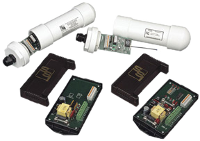
PRL-900 Wireless Pulse Link
The PRL-900 wireless pulse link solves your short-hop pulse connection problems. No more worrying about getting pulses across a parking lot, vacant lots or other obstacles. Now you will be able to connect KYZ pulses between your meter’s pulse initiator and your destination device without trenching or other costly methods of getting wires strung between the two devices. The PRL-900 Wireless Pulse Link system consists of a PRT-900 Transmitter and a PRR-900 Receiver. The system operates at 916MHz and allows unlicensed operation by the user. The PRL-900 will transmit pulses up to 1000 feet in a line-of-sight configuration. Longer distances may be possible with greater elevation above the ground.
The PRT-900 transmitter contains four Form A or two Form C input channels. The transmitter consists of a PRT-2 transmitter base unit where all connections are made and a PRT-900 transmitter/antenna unit which contains the radio transmitter. The PRT-900 is intended to be mounted outdoors, in direct line-of-sight with the PRR-900 receiver/antenna unit and should not be obstructed by trees, buildings or other objects. Each time a pulse is output by the meter’s pulse initiator, the transmitter validates this pulse and sends a pulse out to the receiver. Redundant communications of pulses are used to ensure the accurate number of pulses are sent. The PRT-900 consumes extremely low power and can be operated in either the normal mode or the low-power mode for use with batteries or solar panels, or in applications where pulse speed is not greater than one pulse per second. The normal-mode pulse rate can be as high as 4pps for Form C and 2pps for Form A. The PRT-900 has a built-in low voltage transformer-isolated power supply generating a +13VDC sense (wetting) voltage. The sense voltage is connected to pulse sending devices, typically an electric meter’s KYZ pulse initiators.
PRR-900 ReceiverThe PRR-900 receiver contains up to two solid state KYZ Form C outputs. Each output operates independently according to the state of the input of it’s respective transmitter channel. Each time a pulse data packet is received from the Transmitter, the receiver will validate the pulse and switch the respective output to the correct pulse state. The PRR-900 contains a software algorithm which detects missing pulses and corrects the pulse count should a pulse transmission ever be interrupted. The outputs’ pulse widths should be nearly identical to the pulse widths seen at the transmitter’s inputs, providing not only the correct energy consumption information but correct demand information as well.
*Both the Transmitter and Receiver are capable of operating on supply voltages of 120 VAC, 208-277 VAC.
| Electrical | |
|---|---|
| Power Input: | 120 VAC, 208-277 VAC. Burden: <10 mA at 120 VAC |
| Signal Input to Meter: | +13VDC wetting voltage generated by the PRT-2 Transmitter Base unit. |
| Output: | Two sets of dry Form C contacts (K, Y, & Z) for energy pulses. The contacts are solid state “no bounce” relays rated at 350 VDC or 250 VAC 1/10th Amp. Factory fused at 1/10 amp. (3AG) |
| Output Contact On-State Resistance: | 18 ohms typical, 25 ohms maximum |
| Operate and Release Time: | 1 to 3 milliseconds typical for solid state relay; Total propagation time up to 100mS. |
| Input/Output Isolation Voltage: | 2500V |
| Mechanical | |
|---|---|
| Mounting: | Any position |
| Size: | 3.27” wide, 5.65” high, 1.50” deep |
| Weight: | 2 pounds each |
| Temperature | |
|---|---|
| Temperature Range: | -38º C to +70º C, -38.4º F to +158º F |
| Humidity: | 0 to 98% non-condensing |
| Available Options | |
|---|---|
| Input Voltages: | Contact Factory |
All specifications are subject to change without notice.
