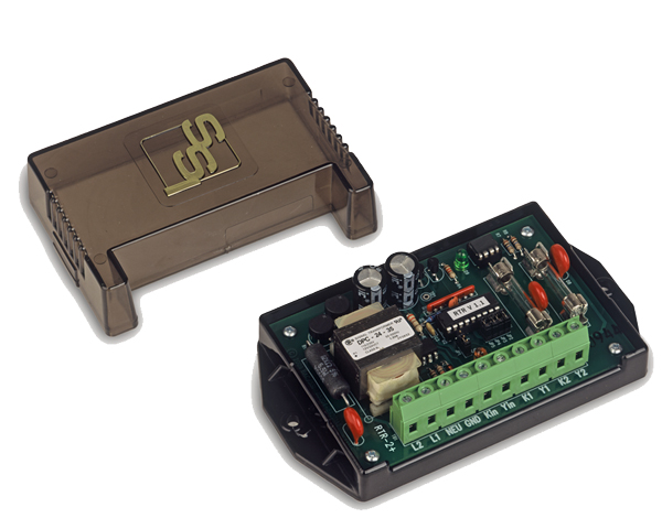
RTR-2+ Water & Gas Meter Relay
B Series
The RTR-2+ High-Speed Repeating Pulse Relay is designed to interface pulse output from water or gas meters to other systems. The RTR-2+ is configured with a Form A input and two Form A (KY) isolated solid-state dry contacts. Most water and gas meters with a pulse output will directly interface to the RTR-2+’s input, whether it is an open-collector transistor, open drain FET, MOSFET solid state relay, read reed switch or a dry-contact relay. The input is activated when the input (Y) is switched from its “pulled-up” state to ground (K) for at least a minimum pulse time. Four input filter times are field-selectable: 50 microseconds, .5, 5 or 20 milliseconds.
When the RTR-2+ relay is inserted in the two-conductor cable between the water or gas meter and the remote equipment, the RTR-2+ provides a replicated signal to the remote equipment, and also provides a separate isolated (dry contact) Form A contact for use with customer-owned monitoring equipment.
Typical applications involve pulse counting, monitoring and recording of water or gas usage. Other applications include interfaces between utility metering devices and customer-owned building automation systems, control and monitoring systems, usage recorders, automated meter reading systems and supervisory control and data acquisition systems (SCADA). Bright yellow LED lamps, one the RTR-2+’ inputs indicate the input’s status at all times, thus allowing the field technician to visually observe pulses being received from the water or gas meter. A bright green LED visually shows the output’s status. No specialized test equipment is required. The microcontroller-based RTR-2+ checks each incoming pulse for its duration. If the incoming pulse is less than the input filter time selected, the RTR-2+ assumes the incoming pulse to be noise and it is rejected. Thus, any valid pulse rate of 200 pulses per second or less is accepted while static and induced high frequency noise is rejected. If used in a very noisy environment this “pulse acceptance window” may be lengthened or shortened as needed to reject noise by selecting a different input filter time.
The RTR-2+ has two modes on the output operation: normal and fixed. The normal mode’s output follows the input so the duty cycle on the out is a mirrored image of the input and timing is approximately the same. In the fixed mode, an output closure time is selected and the output closes for a fixed time period. Each channel of the RTR-2+ has an independently selectable output closure time 5, 10, 20, 50, 100, 200, 500, or 1,000 milliseconds, regardless of the input pulse’s duration. The output duration time may be easily selected on a DIP switch. In this way, pulses can either be “stretched” or shortened to suit the receiving equipment. In the event that the input pulse rate exceeds the output time such that input pulses are arriving from the meter faster than the output can handle, the microcontroller stores up to 65,535 pulses and outputs them in a 50/50 duty cycle as soon as possible so that no pulses are lost. If more than 65,535 pulses are stored, then a RED LED lights indicating a count register overflow.
The RTR-2+ therefore provides a contact closure of sufficient and fixed length to the remote equipment & allows the revenue water or gas meter display to operate normally. The input and output terminal strip is a “Euro” type connector for easy field wiring and excellent isolation. The “K” lead of the RTR-2+’s outputs are fused to prevent damage to the relay under almost any conditions a user might cause such as excessive current, incorrect wiring, etc. RTR-2+ models have built-in transient protection for the solid-state relay’s contacts that eliminates the need for external or off-the-board transient suppressors.
Specifications
| Electrical | |
|---|---|
| Power Input: | 90-130, 208 to 277 VAC. Burden: <10 mA at 120 VAC |
| Pulse Inputs: | One Form A (KY) pulse inputs with a +8 to +13VDC wetting voltage. Current source inputs provide for fixed current through meter contact at approximately 10-20mA. |
| Pulse Output: | Two sets of dry Form A (K & Y) contacts. Outputs are activated (closed) for a nominal 5, 10, 20, 50, 100, 200, 500 or 1000mS following a valid input pulse as selected. The contacts are solid state “no bounce” relays rated at 250 VAC/VDC @ 1/10 Amp. The maximum rating of the contacts is 800mW. Factory fused at 1/10 amp. (3AG) |
| Contact On-State Resistance: | 25 ohms maximum, 18 typical |
| Operate and Release Time: | Turn On: 5 mS maximum, 2-3 mS typical
Turn Off: 5 mS maximum, 2-3 mS typical |
| Input/Output Isolation Voltage: | 2500Vrms |
| Mechanical | |
|---|---|
| Mounting: | Any position |
| Size: | 3.27” wide, 5.65” high, 1.50” deep |
| Weight: | 13 ounces |
| Temperature | |
|---|---|
| Temperature Range: | -38º C to +70º C, -38.4º F to +158º F |
| Humidity: | 0 to 98% non-condensing |
| Available Options | |
|---|---|
| Input Voltages: | 125 VDC input using the DSC-1 Power Supply. |
| Input Configurations: | Sourced Voltage inputs are available which receive a voltage from +3 to +48VDC from external systems. Super low current (FET transistor) input for input current up to 1mA. |
All specifications are subject to change without notice.