PRL-1200 Wireless Pulse Link
The PRL-1200 wireless pulse link is primarily a point-to-point system with one transmitter and one receiver for short-hop pulse applications like parking lots, fields, roads, railroad tracks or anywhere where it is difficult to get a KYZ pulse from the meter. Using Frequency Hopping Spread Spectrum (FHSS) technology allows excellent reliability and rejection of any other noise sources. There are 6 channels and each channel incorporates 25 of the 32 possible frequencies within the 900 MHz band. The same channel is selected on both the transmitter and receiver. Other PRL-1200 systems within the same radio airspace (~2 mile radius) will need to be on a different channel number. Each Transmitter and Receiver are “paired-up” such that the Receiver will only accept pulse meter data from its specified Transmitter.
The PRL-1200 can transmit either 2 Form C (3-wire) pulses or 4 Form A (2-Wire) pulses. Approximately 4 pulses per second (Form C) while 2 Form A pulses are possible which should be more than acceptable for most pulse applications.
The PRL-1200 Wireless Pulse Link system consists of one PRT-1200 Transmitter and one PRR-1200 Receiver. The system operates in the 900MHz band, and is FCC certified, thus allowing unlicensed operation by the user. The PRL-1200 will transmit pulses up to 5,000 to feet in a line-of-sight (LOS) configuration. Distances vary with the terrain, obstacles and greater elevation above the ground.
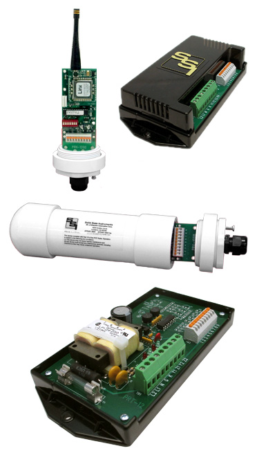
PRT-1200 PULSE RADIO TRANSMITTER UNITThe PRT-1200 Pulse Radio Transmitter unit is made up of two parts: The PRT-12 Transmitter Base unit and the PRNT-1200 Transmitter Radio/Antenna unit which contains the radio transceiver and the antenna. The PRT-12 Base has a built-in low voltage transformer isolated power supply generating a +13VDC sense (wetting) voltage. The sense voltage is connected to pulse sending devices, typically an electric meter’s KYZ pulse initiator. Each time a pulse is received by the PRNT-1200, it validates the pulse width and transmits the pulse to the Receiver. Propagation delay is very short so the pulse output at the Receiver closely resembles the pulse widths received from the meter. The PRT-1200 can be operated using 120V or 277V AC line power or a +12VDC voltage source like SSI’s SPS-1 solar power supply.
PRR-1200 PULSE RADIO RECEIVER UNITThe PRR-1200 can be configured as 2 Form C or 4 Form A output channels and acts as the Receiver. The PRR-1200 consists of a PRR-12 Receiver Base Unit where all connections are made and a PRNR-1200 Receiver Radio/Antenna unit which contains the radio transceiver and antenna. The PRNR-1200 is intended to be mounted outdoors, in direct line-of-sight with the PRNT-1200 radio/antenna unit and should not be obstructed by trees, buildings or other objects. Each time a pulse is received from the PRT-1200, the Receiver validates this pulse and outputs it’s respective output channel. An encoded FHSS communication scheme is used to ensure the accurate number of pulses are sent and received. The PRR-1200 consumes extremely low power and can be operated using 120V or 277V AC line power or a +12VDC voltage source. The pulse rate is up to 4pps (Form C).
**Both the Transmitter and Receiver units are capable of operating on supply voltages of 120, 208-277VAC, as well as +125VDC, +12VDC, and +15 to +48VDC by employing the special SSI power supply options.
Specifications
| Electrical | |
|---|---|
| Power Input: | 120VAC, 208-277 VAC Burden: <10 mA at 120 VAC |
| Input Wetting Voltage to Meter: | +13VDC wetting voltage generated by the PRT-12 Transmitte Base unit. |
| Output: | Four sets of dry Form A contacts (K & Y) for energy pulses. These can be configured as two sets for dry Form C contacts. The contacts are solid state “no bounce” relays rated at 350 VDC or 250 VAC 1/10th Amp, 800mW max. Factory fused at 1/10 amp. (3AG) |
| Output Contact On-State Resistance: |
18 ohms typical, 25 ohms maximum |
| Operate and Release Time: | 1 to 3 milliseconds typical for solid state relay; Total propagation time up to 20mS. |
| Input/Output Isolation Voltage: | 2500V |
| Mechanical | |
|---|---|
| Mounting: | Any position for base units; Must be line of sight for transceiver/antenna units |
| Size: | 3.27” wide, 5.7” high, 1.50” deep |
| Weight: | 2 pounds each |
| Temperature | |
|---|---|
| Temperature Range: | -38º C to +70º C, -38.4º F to +158º F |
| Humidity: | 0 to 98% non-condensing |
| Available Options | |
|---|---|
| Input Voltages: | Contact Factory |
| Enclosures: | 10” x 8” x 4” NEMA 4X Fiberglass Enclosure for Base Units |
All specifications are subject to change without notice.