2-Wire or 3-Wire... That is the Question
May 2012
|
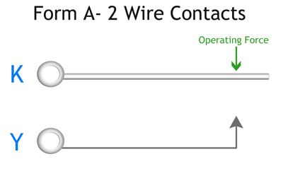
Probably the most confusing part of Pulse Metering is the misunderstanding of 2-wire and 3-wire pulse values. Almost universally, pulse metering revolves around 3-wire pulse values given that historically it took 3-wires for pulse metering to work. Over time, pulse metering has become mostly a two-wire methodology. While we are at it, we should mention that 2-wire pulse metering is also called Form A, while 3-wire is referred to as Form C. This terminology comes from the IEEE standard definitions for switch and relay forms. Form A has Single-Pole, Single Throw (SPST) Switch contacts – a Common terminal and a Normally-Open terminal -- and thus 2 wires. (roll over image below to activate switch)
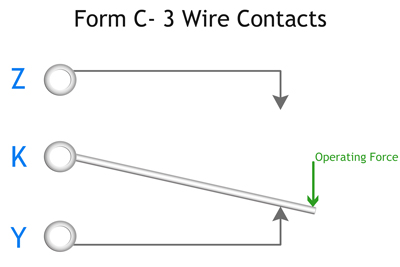
Form C on the other hand is a Single Pole, Double Throw (SPDT) format that has a Common terminal, a normally-open terminal and a Normally-Closed terminal, and thus 3-wires. These three terminals are referred to as K, Y and Z, where K is the common terminal of the switch, Y is the normally-open contact, and Z is normally-closed contact. All pulse metering is based on these two contact forms. A little confusing but stick with us!
Our purpose here is to demystify pulse metering, “pull back the curtain” and allow an understanding of the non-hardware part of pulse metering. We’ve defined the hardware part of pulse metering above as a switch. Of course, this switch closes (and opens) in proportion to energy use. So what does each closure of the switch mean? How does this work? |
Explaining 2-wire and 3-wire values:Since pulse metering originally used 3-wires and each of the active wires (Y and Z) were monitored for one transition of each, that allowed the original definition of a pulse as “any transition of the KYZ switch”. There are only two possibilities here, either the K to Y continuity opens, and the K to Z continuity closes; OR visa-versa. In each and every transition K-Y closes, K-Z opens, or K-Y opens and K-Z closes. In any case, each transition is worth so many kilowatt-hours or watt-hours of energy use. This is referred to as the pulse constant which is determined by the metering package. In the figure below you can see each transition, signified by the green arrow. You’ll notice that we’ve designated the low-to-high transition on the diagram below which represents the open-to-closure of the switch. We’re ASSUMING that the downstream piece of equipment receiving the pulses is only looking at the low-to-high transition and ignoring the reset or return “edge” of the closure (opening). This assumption is generally true but not always. Let’s assume that there are 8 transitions, and let’s further assume that each transition is worth 64 watt-hours per pulse (pulse constant). For the 8 pulses that have occurred, the total energy monitored for this time is 8 x 64 or 512 watt-hours or .512 kilowatt-hours. 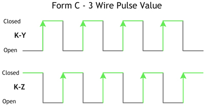
|
Why 2-Wire instead of 3-Wire?Now, as mentioned above, the world seems intent on using 2 wire pulses. There are a number of reasons for this. First of all, electronics has improved substantially with filtering techniques. For example, digital filtering techniques have allowed pulse receiving equipment designers to get the same reliability with less cost by only using 2 wires. In the figure below, we see the same pulse diagram, but only one side, Y or Z, is used. It doesn’t matter which side, we can use either K-Y or K-Z, but for this example we will use K-Y. Notice that in this scenario, the downstream piece of pulse receiving equipment is monitoring only one direction of the K-Y side so there are half as many pulses. Therefore, to monitor the same amount of energy use with the 4 transitions of the KYZ switch using only two wires, the pulse constant (Pulse Value) must be doubled. In this scenario, we have to use a value on the pulse receiving equipment of 128 watt-hours per pulse (64 x 2). Since there are only 4 transitions over this time period, and thus only 4 transitions seen by the pulse receiving equipment, the energy monitored is 4 X 128 = 512 watt-hours per pulse. 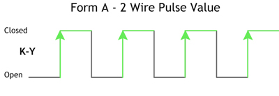
So you can see that the real issue of two or three wire KYZ pulses is the way the downstream piece of equipment interprets the pulses. |
But Wait...Sounds simple, but there is one more possibility. What do you do if the downstream (pulse receiving) piece of equipment separately monitors both transitions of one side? This is somewhat unusual but does exist in equipment that calculates demand. Because demand is calculated each time a pulse is received, better resolution is achieved since “edges” are monitored. See Figure below: 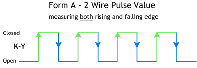
The pulse receiving equipment in this type of application is generally timing from rising edge to rising edge (green arrows), and subsequently, from falling edge to falling edge (blue arrows). (Another way to say this is opening to the subsequent opening, and closing to subsequent closing.) Monitoring in this manner results in better resolution versus monitoring only one edge. In this case, you would have only two wires but would use the 3-wire pulse value. The doubling of 2-wire values for the 3-wire equivalent is not always true but depends on the receiving piece of equipment and how it interprets energy use. In this example, we once again have 8 transitions. There are 4 closures and 4 openings each with 64 watt-hours per pulse. Even though we only used two wires, we counted a total of 8 pulses that occurred in the same time frame. Therefore, we have the same total energy monitored for this time of 8 x 64 or 512 watt-hours or .512 kilowatt-hours. Although pulses are a fairly simple way of monitoring energy, it can be a somewhat convoluted topic when you start adding the various elements and forms available. Hopefully we’ve helped simplify the difference between 2-Wire and 3-Wire pulse configurations and how they function. We’d also like to thank Mark Clark from AEP in Roanoke, VA for suggesting this newsletter topic, specifically the unique situation where both the rising and falling edges can be monitored. If you have a pulse-related topic that you'd like to discuss or suggest for our newsletter, please feel free to drop us a line at info@solidstateinstruments.com. |
Taking your Pulses Further
Little Relays that Pack a Punch!