Line Voltage Isolation Relays are Problematic for Modern Meters
August 2015
|
Today, many utilities continue to do KYZ metering installations the same way they were done 30 and 40 years ago. Yes, they may still work, but it is not the best engineering solution due to changes in the meter’s KYZ outputs. In addition, the long-term reliability of the meter’s pulse output is compromised. Let’s look at this more closely. The classic KYZ pulse circuit involved a mechanical pulse initiator – a single-pole, double-throw (SPDT) switch – in the meter and an isolation relay with latching mercury-wetted relays. This was the best and most noise-immune scheme available at the time. Line voltage, normally 120VAC (and sometimes 277VAC) was used as the “wetting voltage” across the pulse initiator. This was a good solution since 120VAC was readily available at the meter and the KYZ switch could easily handle the voltage. A transient suppression snubber network, a resistor and capacitor in series, was put in parallel with the contacts to suppress arcing on the mechanical switch. All in all, transients were not a big problem because the circuit contained a mechanical switch and two coils. 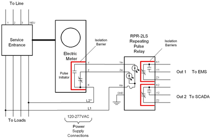
In the drawing above you can see the source, the switch, and the load, the elements needed for a circuit. The source is the 120VAC wetting voltage. The switch is the KYZ pulse initiator in the meter. The loads are the two relay coils of a latching mercury-wetted relay, commonly used in the KYZ pulse metering circuit. As the meter disc turned, a cam on the vertical axis alternately switched the SPDT pulse initiator switch from K-Y continuity to K-Z continuity. Since this was a SPDT switch, 120VAC was alternately routed to the two relay coils, which meant that only one coil could be energized at a time. In a mercury-wetted latching relay, one coil was the set coil and the other was the reset coil. Applying the wetting voltage to the set coil resulted in setting the contacts in the K-Y continuity position. This was analogous to the normally-open contact being closed. Applying the wetting voltage to the reset coil resulted in resetting the contacts back to the K-Z position. Since the relay was a latching design, this eliminated contact bounce and was a very, very robust noise immunity scheme. One of the things that made this scheme so robust and reliable was the fact that all these components were electro-mechanical in nature and, as such, were imperious to lightning and transient voltages on the power lines. Now, fast forward many decades. In the 80’s and 90’s, meter manufacturers started experimenting with solid state pulse initiators. This was driven by the long, arduous process of transitioning meters to fully solid state, a meter that had no moving parts – no rotating eddy current disk, no vertical axis, no cam, and no KYZ SPDT mechanical switch. So the process of creating a pulse became electronically synthesized. The SPDT mechanical switch was replaced by an electronic switch. The type commonly used today in all of the solid state meters’ KYZ output board is an optically-isolated MOS-FET solid state relay. Solid state, by nature, is much more sensitive to lightning, transient voltages, and disturbances on the power lines. Great efforts are made by all electronics manufacturers to make sure that lightning, static discharge, and transient voltages do not affect their device. This takes a good understanding of the kinds of voltages, currents, and environmental factors that will be present when such an event takes place. Unfortunately, in most KYZ pulse applications, these details are not always known. The utility generally gives the customer the K, Y, and Z wires and says “Here it is. Hook up your equipment.” With an older meter, this would not present a problem due to the robust nature of the electromechanical components. However, today that pulse circuit may or may not last depending on the application environment and specifics of the installation. The ideal solution to this problem is to use a low wetting voltage relay. These relays incorporate a transformer-isolated DC power supply that provides a current-limited and transient-protected +13VDC to the meter. Using a low DC voltage is a better solution to the problem for three important reasons:
In the pulse metering circuit shown in the figure below, all the same wires are used but are wired in a different configuration to the low voltage relay: 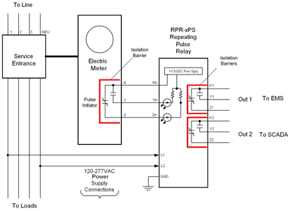 | |
By using low voltage isolation relays, reliability is improved and the meter is better protected. The low voltage isolation relays are compatible with all known KYZ outputs currently being offered on electric meters. At least one meter manufacturer recently replaced a 350V part to a 250V part, even though a high voltage rating is critical for the relay’s survival in the field. At least a 400V rating on the solid state relay is required for 120VAC voltages. Anything less will compromise reliability and survivability. However, low voltage isolation relays are a perfect solution for this, and all types of modern meters, which is why SSI has discontinued offering line voltage relays in favor of the more reliable low voltage isolation relays. Utilities may want to consider changing to low voltage relays to improve reliability extend the life of today’s solid state meters. | See Also:Low Voltage Pulse Isolation Relays September 2012 Newsletter |